Pricing and specifications subject to change without notice.
USING
NaP3 With LP-PAN
Installation, Setup and Operation Guide
Image shown below is from beta v1.0.0. Other pictures are from the beta 1.04. The current version is the v2.4.0, released Nov. 30, 2014. The images on this page have not been updated to reflect the latest version, yet. We will update the page as soon as possible. In the meantime, you can download the latest version here. Note: If you are running LP-Bridge or LPB2, you should use the latest releases, found here. Previous versions of all LP programs can be found in this folder, http://www.telepostinc.com/Files/
The pictures are reduced in size to fit on this page, with some loss of detail due to compression.
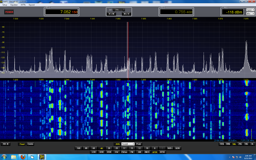
Above
picture is NaP3 in Collapsed mode. This mode allows most of the controls to be
hidden. In this example, the VFO, band and mode buttons are enabled, and the
rest hidden.
I provide this page as a way to help users who want to use this program with LP-PAN. I have no official connection to Pete or the program other than offering suggestions and help with testing.
NaP3 will communicate directly with various rigs, including K3, Kenwood and recent Yaesu rigs (FT-950, 2000, 5000). It will also communicate with the rig through LP-Bridge or LPB2, which greatly extend the capability of the rig by allowing multiple applications to easily connect to the rig and share its serial port. LP-Bridge only supports Elecraft K3, while LPB2 works with all the rigs that NaP3 supports, including K3, plus it adds support for Elecraft K2. LPB2 has a couple minor limitations compared to LP-Bridge, but both should work well for most users.
Support questions can be sent to N8LP, or can be posted to the LP-PAN User Group.
73,
Larry N8LP
*On this page and web site, all references to PowerSDR apply to FlexRadio Systems PowerSDRTM program. Support questions for the various PowerSDR based open source programs referenced here, should not be directed to FlexRadio Systems, but rather to the specific author of the modified version, or to N8LP, or the LP-PAN User Group.
NaP3 Installation
NaP3 Setup and Configuration - Generic
NaP3 Quick Setup - K3 and E-MU 0204
NaP3 Quick Setup - FTdx5000 and E-MU 0204
NaP3 Quick Setup - FT950/2000 and E-MU 0204
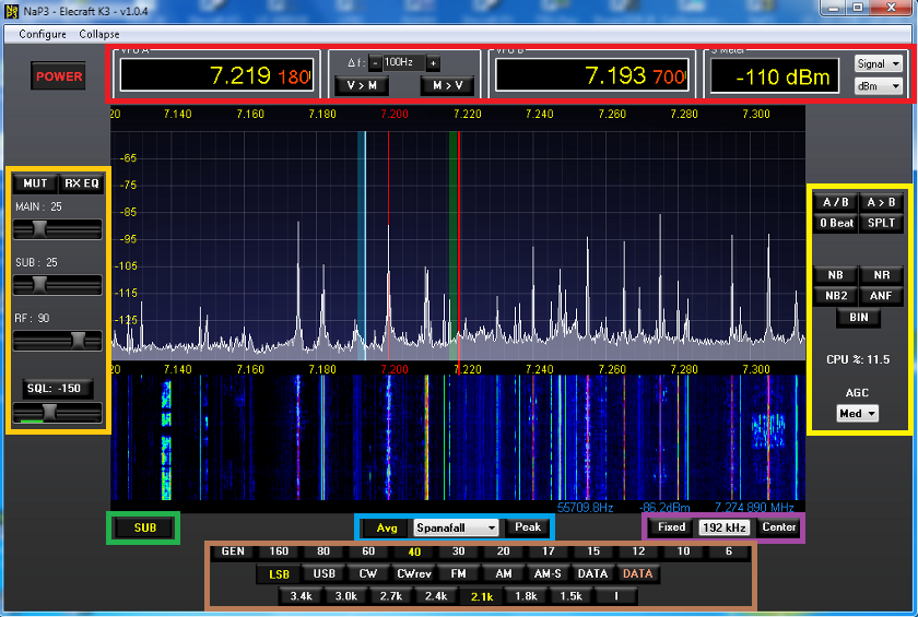
Above picture is NaP3 in Expanded mode. This mode shows all of the controls. Color overlays have been added to aid with the description of controls which follows.
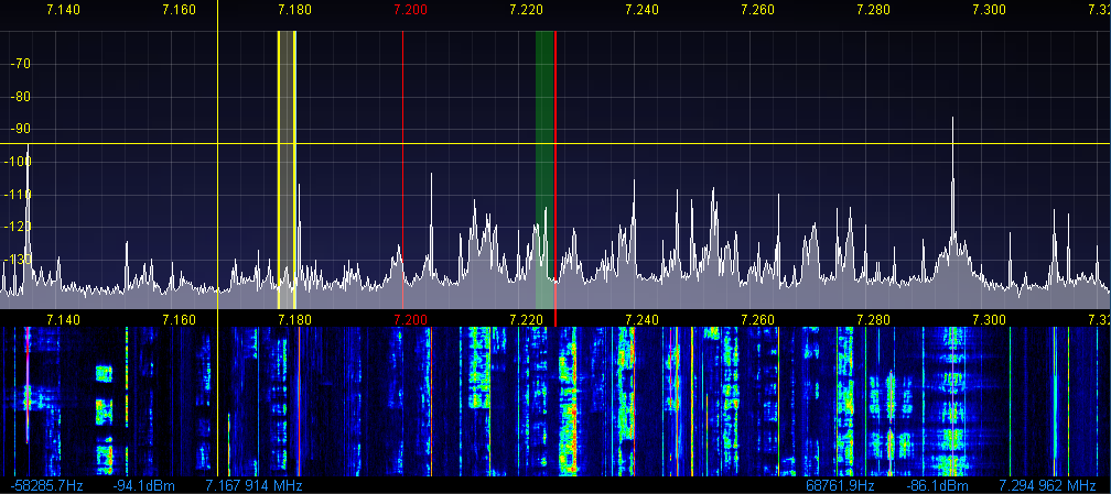
Above
picture shows a section of NaP3 pan in Fixed mode, which locks the background
in place while allowing the two VFOs to be tuned separately over the background.
Filter overlays for VFO A Main (green) and VFO B Sub (yellow) are also shown.
They are currently only fully linked to the rig if it's a K3, but support for
the other rigs is in the works. Also shown is VFO B transmit cursor in
split operation (yellow lines). The yellow crosshairs indicate the mouse cursor
position. They change to red when adjusting VFO B. Note:
Some of the colors have been changed in Setup from the defaults.
The blue numbers below and at the left side of the window represent the frequency offset, signal level and absolute frequency of the crosshairs position. The ones at the right side represent the frequency offset, signal level and absolute frequency of the strongest signal in the window.
The blue numbers below and at the left side of the window represent the frequency offset, signal level and absolute frequency of the crosshairs position. The ones at the right side represent the frequency offset, signal level and absolute frequency of the strongest signal in the window.
Overview of Controls:
Refer to the above picture for a description of the controls. Color overlays are used to explain button functions by section. Carefully read the whole section because there are a number of not so obvious controls which are revealed as context menus when right clicking some of the buttons shown.
Power... Starts and stops processing.
Configure...
This pulldown menu has four choices...
Setup, allows detailed setup of all parameters, arranged into 7 different tabs. A thorough discussion of each tab is presented further down this page.
Equalizer, allows setting of the multiband equalizers for receive audio contouring.
XVTR, allows setup of the transverter band buttons.
Show XVTR Buttons, toggles between HF and XVTR buttons.
Collapse/Expand...
Toggles to the collapsed view which hides many of the controls and allows the pan window to fill the screen. Some of the other controls can be selectively added back based on the settings in the Options tab in Setup.
| RED
SECTION |
VFO A, shows current rig main VFO frequency. Can be changed by entering a frequency, adjusting mousewheel or pointing and clicking in the display. Right clicking in the display will add yellow crosshairs. Placing the crosshairs over a signal and left clicking will cause the rig to jump to the signal. Right clicking again will turn off the crosshairs, or change them to red if SPLIT or SUB is on. Left clicking with the red crosshairs will cause VFO B to jump to the signal's frequency. Adjusting the mousewheel will fine tune. The frequency offset, signal level and absolute frequency of the crosshairs position is displayed below the pan window at the left of the screen in small blue letters..
Delta F, aka mousewheel tuning step size lets the user determine the rate of mousewheel tuning.
V>M & M>V, are used to save and recall memory frequencies. When using these, another window is opened up where the user can see all memory frequencies and add/edit information about each one.
VFO B, see VFO A explanation
S-Meter, can be set to read Avg or Signal, dBm or S-Units.
| ORANGE
SECTION |
MUT, mutes the audio output of the software.
RX EQ On/Off, enables the EQ settings that are set in the equalizer. The equalizer itself can be accessed by selecting Equalizer in the menu bar.
RX A and RX B audio gain controls, are used to adjust the audio output levels of the main and sub receivers. A feeds the left channel and B feeds right channel of your sound card outputs. When the subreceiver is not enabled, or SPLIT is not enabled, RX A feeds both outputs.
RF gain, works like the RF gain control on a real radio. Sets the threshold where AGC action starts.
Squelch On/Off and Threshold, works like a normal squelch. Pressing the button turns it on. Sliding the slider adjusts the threshold. The little S-Meter below the slider aids in setting the threshold. Used mostly for FM.
| YELLOW
SECTION |
A/B toggles VFOs
A>B copies VFO A to VFO B
SPLT turns on split VFO operation and activates the TX passband indicators (vertical yellow lines). Clicking on the SUB button will also overlay the sub-receiver passband indicator. These indicators will also track the RIT/XIT and DSP filter settings if you have a K3 so that the TX and RX passbands will always be correct.
0 Beat, causes the signal to be centered in the passband. Used mostly for CW.
NB / NB2, turns on digital noise blankers. Extensive settings for these can be found on the DSP tab in Setup. This control, and the following four controls do not change any parameters in the rig. These affect the audio output of NaP3, as heard on the sound card speakers/headphones.
DNR, turns on digital noise reduction. Extensive settings for this are found on the DSP tab in Setup.
ANF, automatic notch filter. Automatically detects and notches out the strongest offending carrier in the passband. Extensive settings for this are found on the DSP tab in Setup.
BIN, binaural mode. Creates a stereo field of signals based on frequency and phase to position signals between the user's ears.
AGC, sets the decay for the AGC. Extensive settings for this are found on the DSP tab in Setup.
| GREEN
SECTION |
SUB, turns on the NaP3 subreceiver as well as the rig's subreceiver if you have a K3 with KRX3. The SUB frequency is linked to the rig's VFO B frequency. When the subreceiver is ON, a subreceiver passband indicator is added to the pan display.
| BLUE
SECTION |
AVG, is a dual function button...
1) Left clicking turns on averaging of the pan trace. The amount of averaging is determined by the Span setting and the base value entered in Setup.
2) Hovering over the button allows mousewheel adjustment of the display levels. This changes the Grid Min/Max, Waterfall Low/High levels in Setup and is saved per band. The range between max/min & high/low remains that which is set in Setup.
Center, pulldown menu, selects the display type... Spanadapter, Scope, Waterfall, Spanafall, Phase, etc.
Peak, is another dual function button...
1) Turns on peak hold of the pan trace.
2) Hovering over the button allows mousewheel adjustment of the pan/waterfall proportions when in Spanafall mode.
| PURPLE
SECTION |
Fixed, turns on Fixed Tune mode which locks the pan background to a user set frequency range, and allows tuning of VFO A and VFO B over the top of the background, as opposed to normal operation where VFO A is always centered and the pan moves behind it. When tuning to the edge of the screen, the background jumps to a new segment. When using 192kHz Span, half of the display is greyed out for technical reasons related to concept of the fixed mode.
Span, selects the span width of the display. Hover the mouse pointer over the box and use the mousewheel to change span. You can also use the Page Up and Page Dn buttons on your keyboard to do this. When zoomed in to very narrow span, it helps to have the Buffer Res. on the DSP tab in Setup set to 16384 or 32768 for best signal separation and detail.
Center, allows easy recentering of the display.
| BROWN
SECTION |
Band buttons, select HF band buttons, or XVTR buttons, depending on the setting of the Display XVTR Buttons choice in the Configure menu. They also recall modes as saved by the band stacking memory.
Mode buttons, are used to select mode. Right clicking on DIG L or DIG U opens up a menu to allow selecting a data sub-mode (currently only supported for K3).
Filter buttons, allow setting of the bandwidth presets. If the rig is set to a width between these, the last button is automatically selected. Right clicking on any of these allows the user to set a custom width, shift and name for each button on a mode by mode basis. This is a very powerful feature.
_____________________________________________
NaP3 Installation
Pete, F5VNB, the author of NaP3 recently pulled the latest version (v2.4) due to the difficulty in supporting the app with the wide variety of expectations and systems in use. The last version I have is v2.2.4.2 beta...
NaP3 v2.2.4.2 beta Installation Package
This is what I have been running for quite some time. I will speak to Pete about which version he feels is the most stable and best to post.
A legacy version of NaP3 is still available here...
NaP3 v1.2.5.7 Installation Package
Note: If you are running LP-Bridge or LPB2, you will also need to upgrade those. K3 users should update LP-Bridge to v1.08 to take advantage of all the new features of NaP3, http://www.telepostinc.com/Files/LP-Bridge_108_update.zip . You will have to update to the full version v1.07 first, http://www.telepostinc.com/Files/LP-Bridge_107_full.zip .
For non-K3 users, the latest version is v1.06 full, http://www.telepostinc.com/Files/LPB2_106_full.zip
Note: Be advised that the new versions all use the latest Eltima drivers, which makes loading of LPB slower than the older versions, but makes them windows 8 compatible.
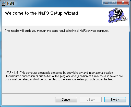
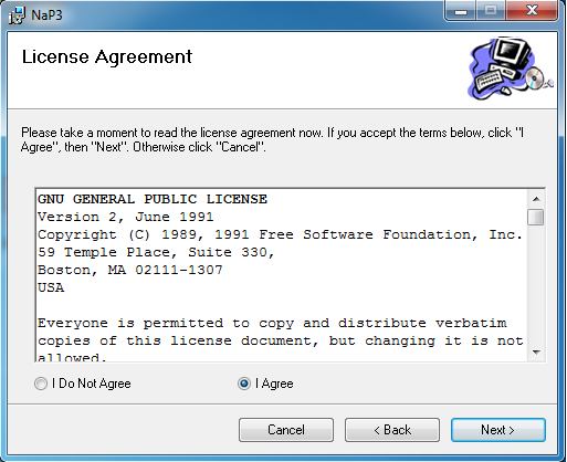
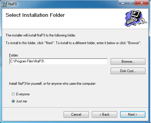
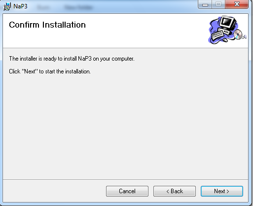
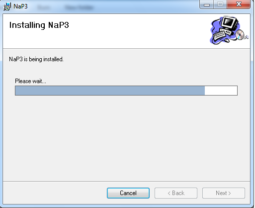
Unzip the folder and run the Setup.exe or Setup.msi file. You will see the following screens during installation...
Follow the directions and accept all the defaults. Note: If you already have a version of NaP3 installed, you will see an additional screen which will ask you if you want to repair or remove the existing version. If asked about replacing an existing file with an older one, always keep the newer file. When asked whether to allow access to the program to "Everyone" or "Just Me", your choice will affect access to the program and the path to where the database files ( with all the settings) will be placed. With Everyone it will be placed in your Users\AllUsers\AppData\ path. With "Just Me" it will be placed in your Users\<your username>\AppData path. To avoid confusion, we recommend the "Just Me" choice.
 |
 |
 |
 |
 |
 |
After closing Setup and launching the program for the first time, it will run a one time check of forward and reverse FFTs. Here's a picture of the screen you will see during this process...
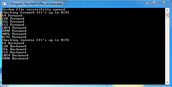
Just click OK to close the warning screen that accompanies this. When it finsihes, the program will start. Proceed to the next section for initial setup.
_____________________________________________
NaP3 Configuration:
(Pictures compressed and reduced in size to fit better on this page).
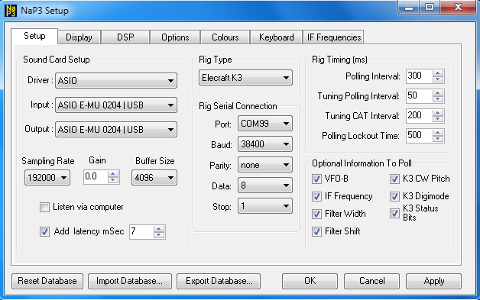 Setup tab... Setup tab...Sound Card Setup... Driver: The best choice is usually ASIO as it is the most modern. When sharing the sound card with CW Skimmer, MME is usually the correct choice, depending on sound card. Input / Output: Select your sound card from the available choices. MIxer: Select None. Sampling Rate: Set for the highest rate supported by your card. Gain. Adjust to provide the correct reading on the S-Meter or pan display based on a calibrated signal source. Short of having a calibrated signal source, use this to match your rig's S-Meter reading on a stable carrier. Buffer: The default is 2048. 4096 may provide a more stable stream, but will add a little to the delay in sound compared to your rig. Latency. Check this if you are getting erratic streaming of audio. Defaults to 5ms, but slightly higher settings may be needed. MME driver will require much higher settings of, say, 25ms. Rig Type... Choices are Elecraft K3, TS-940S, TS-950S, Yaesu and No CAT Rig for olders radios such as TS-830S. Note: K2 is also supported by selecting Kenwood in NaP3 and K2 in LPB2. Most Kenwoods with CAT capability will work with one of the Kenwood choices. Rig Serial Connection... Port: Choose the rig port here. Defaults to COM99, which is the port used in LPB2, but can be set to any valid port in the pulldown menu. If you have a different port set up in LP-Bridge, such as COM19, then you would select that here. Baud Rate: Depends on rig. Use the highest setting that the rig supports. If using LP-Bridge, set this to 38400. If using LPB2, set this to the same setting that LPB2 uses to connect to your rig. Parity, Data, Stop: Depends on rig. Defaults to None, 8, 1. Rig Timing (ms)... Polling Interval: Defaults to 300ms. If using LP-Bridge or LPB2, be careful when setting this lower than 300, and never set it lower than the setting in LP-Bridge or LPB2. In general, this should be set about 100ms slower than the LP-Bridge / LPB2 setting. Tuning Polling Interval: Defaults to 50ms. This sets the polling interval while NaP3 is tuning. The faster rate is used to provide smooth tuning. Baud Rate: Depends on rig. Use the highest setting that the rig supports. If using LPB2, set this to the same setting that LPB2 uses to connect to your rig. Tuning CAT Interval: Defaults to 200ms. Polling Lockout Time: Determines the wait before switching from rig control to NaP3 control. Defaults to 500ms. Optional Information to Poll... Mostly self explanatory. Check each box to allow NaP3 to gather the indicated information from the rig. K3 has the most options. IF Frequency provides NaP3 with the required information from K3 to make mode offset adjustments automatic with K3. It also provides the proper correction when the K3's IF shift is adjusted so that pitch does not change in NaP3. Note: The following controls appear on all Setup screens. Reset Database... Resets the database (all settings) to default values, and saves a copy to the Desktop. Import Database... Allows recalling of a saved database from the Desktop. Export Database... Saves a copy of the current database to the Desktop. Useful for restoring the setup if your PC experiences a problem from a hardware failure, system crash, etc. OK, Cancel, Apply... OK closes the Setup window and saves your changes. Cancel closes the Setup screen without saving changes. Apply saves changes without closing the Setup screen. |
 Display
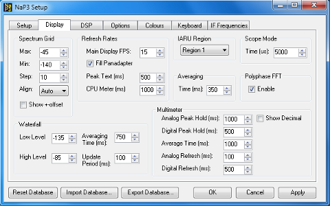
tab... Display
tab...Spectrum Grid... Max, Min, Step: Set the maximum and minimum levels displayed in the panadapter. The difference between them is the range. The step size sets the left hand legend steps on the display. Note: Min and max interact with the minimum level setting on the main screen. Range does not change. These are all saved per band. Align: Defaults to Auto, which is where it should be left except in special circumstances. Show + / - Offset: Check this if your rig does not have CAT control. Displays relative frequencies in the pan window, with "0" in the center. Waterfall... Low Level, High Level: Similar to Min and Max above. I find that setting Low Level 5dB higher than Min setting works well. Also affected by noise floor setting on the main screen (Avg, Ctrl, Mousewheel). Settings saved per band. Averaging Time (ms): Affects the amount of recursive noise reduction in the waterfall. Update Period (ms): Affects the vertical speed of the waterfall. Refresh Rates... Main Display (FPS): Sets the refesh rate of the pan display in Frames Per Second. This can also affect audio streaming quality. If you have streaming issues, try adjusting this. Sometimes a higher setting actually works better for some reason. Fill Panadapter: Checking this adds a solid color below the pan trace. Default color is grey. Peak Text (ms): Sets the update rate for the peak signal readout in blue text just below the pan window. CPU Meter (ms): Sets the CPU Usage display update rate. IARU Region... Sets region for band limit annunciators. Scope Mode... Time (us): Sets the sweep time for the scope display. Defaults to 5000, which is a good setting for monitoring SSB. Averaging... Time (us): Sets the recursive averaging time for the pan display when the AVG button is pressed on the main screen. Polyphase FFT... Enable: Provides improvement in trace resolution in some circumstances depending on Window type set in DSP tab. Multimeter... Adjusts the various timing settings of the multimeter (S-Meter). Self explanatory. |
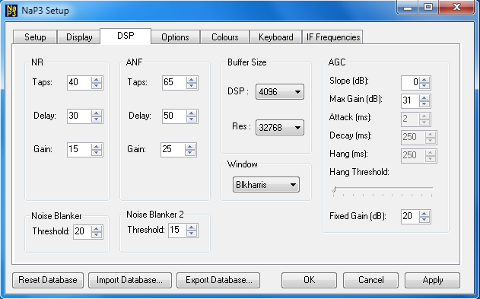 DSP tab... DSP tab...NR, ANF, Noise Blanker 1 & 2, Window, AGC These settings should be left as is unless you understand what they do. Anyone interested in reading about these should refer to the PowerSDR* manual at the Flex Radio website. Buffer Size... DSP: Adjusts the resolution of the DSP processing for filters. Affects filter skirts and latency. Defaults to 4096. Res: Sets the number of samples for FFT. Higher numbers yield better resolution for narrow spans, but also allow the panadapter to show more spurious signals due to increased resolution. Defaults to 16384 (4 times more resolution than PowerSDR*). |
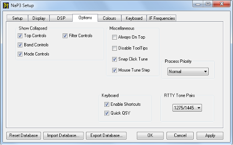 Options tab... Options tab...Show Collapsed... Chooses which controls are displayed in addition to the pan window when Collapsed Mode is selected in the main screen. Miscellaneous... Always On Top: Gives NaP3 priority above all other windows. This can be used to tuck NaP3 inside another program window for a customized look. Disable Tool Tips: Eliminates the tool tips which are displayed when hovering over controls. Once the user has memorized all the controls, this can reduce clutter. Snap Click Tune: Forces mouse clicking to jump to the nearest mouse tune step size. Mouse Tune Step: Displays the mouse tune step size in the VFO area of the main screen. Displays mousewheel and snap click tune size. Process Priority... Should be left on Normal except in exceptional cases. Can cause system instability if set above Normal, but can also improve speed of program response. Keyboard... Enable Shortcuts, Quick QSY: Used to enable keyboard shortcuts, which are set in the Keyboard tab. RTTY Tone Pairs... Determines the Mark/Space tones used in the positioning and click tuning of RTTY signals. |
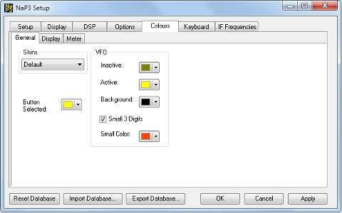 Colours
tab... Colours
tab...This page allows the user to customize many of the colors used in NaP3. Self explanatory. |
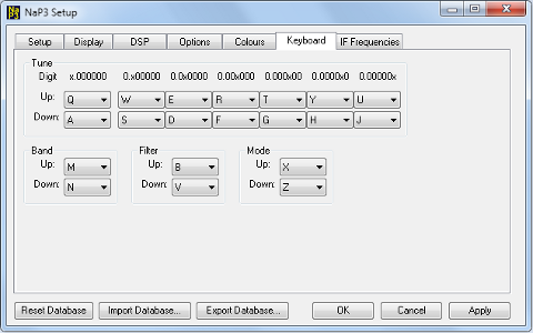 Keyboard tab... Keyboard tab...This page allows the user to map various functions to the keyboard for use when Keyboard Shortcuts is enabled on the Options tab. |
|
Gain adjustment -
To set the gain display accuracy requires a signal source with known output level. This can come from a calibrated signal generator, or something as simple as the Elecraft XG1, XG2 or XG3 test oscillators. This section assumes an XG2 is being used, which has an output of about 73dBm (50uV / S9). Set the K3 preamp and attenuator OFF, and the Preamp setting in NaP3 to MED. Turn Avg. on in NaP3. Connect your generator to the RX ANT input of the K3, and select RX ANT. Adjust your sound card inputs to about 40% of full gain. If you are using the E-MU 0202, set the pots to about the 10 or 11 oclock position. In all cases, the left and right level controls should be set exactly the same. Most software based controls are ganged so that they can be adjusted together. Adjust R29 on LP-PAN to mid scale. These settings should work well for most users. If you find that you need less gain to avoid overload by strong signals, you can turn down the sound card inputs or the LP-PAN gain. If you need more sensitivity, you can increase the sound card inputs, or better still, install the K3 IF buffer mod (available from Elecraft) and/or the LP-PAN preamp. Tune in the XG2 signal at 3.579, 7.040 or 14.060 MHz. The peak on the pan display should be 73dBm. If its not, NaP3 can be calibrated to display the correct level easily.
Click on Setup in NaP3, then adjust the Gain setting in the Sound Card Setup section so that the signal reads -73dBm (S9) in NaP3.
If you have an adjustable signal generator, you can set the maximum signal that LP-PAN can handle without clipping. A good compromise between weak signal display and maximum signal handling is a clipping point of about 10 dBm with the K3 preamp OFF. You will need to jockey the sound card and R29 settings to find the best compromise, and readjust the Gain setting for S9 afterword.
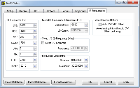
Global Offset and Mode offset adjustments
Refer back to SetupIF pictures of the IF Frequencies tab. If your rig is a K3, all the mode offsets should be set to 0. LP-Bridge provides an offset value to PowerSDR which keeps the IF center frequency of PowerSDR synchronized with the K3. For other rigs, set the starting mode offset values as indicated. It is important that AM be set to 0.
Due to intentional offset of the local oscillator of LP-PAN, and slight variations in the xtals, you must fine tune the software to exactly line it up with the rig. This is done with the Global Offset control. The nominal offset will be 6kHz with newer LP-PANs, but earlier models had various offsets before we standardized on 6kHz. This was done to move the center of the passband slightly to avoid problems with some older or cheaper sound cards which have difficulty near an audio frequency of 0 Hz. On earlier K3 models without the additional offset, the nominal value will be 0. Global Offset is set in the PowerSDR SetupIF window.
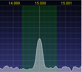
Set your rig to AM mode and tune in an AM signal on a known frequency, like WWV. Zoom the PowerSDR/IF display in all the way. Adjust the Global Offset so that the carrier is centered on the red line in the middle of the display. This is all that is necessary for the K3.
To fine tune the individual mode offsets for other rigs, set the rig to the mode to be adjusted and tune in a carrier for a comfortable pitch. Turn the volume of the sound card monitor up so that you hear the output of PowerSDR at about the same level as the rig. The two tones should be similar, but probably not exactly the same pitch. Adjust the IF Frequency control for each mode to zero beat the tones. Note: Any IF shift or DSP shift controls in the rig will affect the pitch, so make sure that the rig controls are centered when making the adjustments.
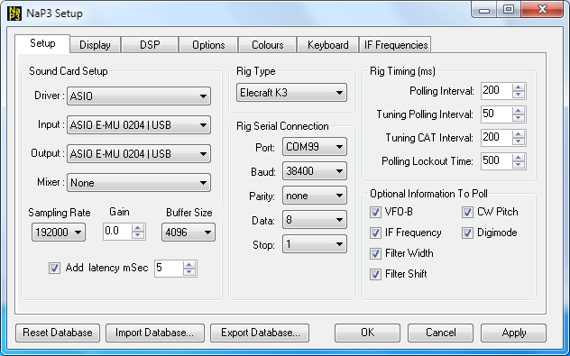
NaP3 Quick Setup - K3 and E-MU 0204 - to get you started. Refer to detailed setup for user preferences and other tabs
|
Setup
tab... Sound Card Setup... If you run CW Skimmer at the same time as NaP3, you should choose MME as the driver and increase Latency to 25ms. Gain. Adjust to provide the correct reading on the S-Meter or pan display based on a calibrated signal source. Short of having a calibrated signal source, use this to match your rig's S-Meter reading on a stable carrier. Buffer: The default is 2048. 4096 may provide a more stable stream, but will add a little to the delay in sound compared to your rig. Latency. Check this if you are getting erratic streaming of audio. Defaults to 5ms, but slightly higher settings may be needed. MME driver will require much higher settings of, say, 25ms. Rig Serial Connection... Port: Choose the rig port here for direct K3 connection. Defaults to COM99, which is the port used in LPB2, but can be set to any valid port in the pulldown menu. If you have a different port set up in LP-Bridge, such as COM19, then you would select that here. Baud Rate: Set to 38400. Make sure the K3 is also set to 38400. Parity, Data, Stop: Depends on rig. Defaults to None, 8, 1. Rig Timing (ms)... Polling Interval: Defaults to 300ms. If using LP-Bridge or LPB2, be careful when setting this lower than 300, and never set it lower than the setting in LP-Bridge or LPB2. In general, this should be set about 100ms slower than the LP-Bridge / LPB2 setting. Optional Information to Poll... Check all of these for K3 unless you don't want to track DSP filter width and shift. Note: Picture might be slightly different than latest NaP3. |
|
Options
tab... Most common setup shown. Additional comments follow... CW Pitch... Leave default value as shown. The K3 is polled for actual pitch. Check Auto CW VFO Offset box RTTY Tone Pairs... Determines the Mark/Space tones used in the positioning and click tuning of RTTY signals. Must be manually set to match the settings in the K3. |
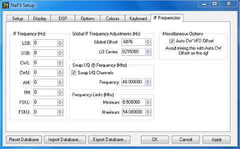 Options
tab... Options
tab...Most common setup shown. Additional comments follow... IF Frequency Adjustments (Hz)... Automatic with K3. Global IF Frequency Adjustments (Hz)... This provides a way to align the local oscillator in LP-PAN with the rig's master oscillator. For most versions of LP-PAN, the setting will be close to -6000 (minus 6000). This is done on purpose to move the center of the IF away from the 0Hz point of the sound card. This can be fine tuned by tuning in an AM signal, and adjusting this setting so that the carrier is centered on the center red line on the pan display. Swap I/Q @ Frequency (MHz): Reverses the sidebands at the indicated frequency. Not needed with all rigs. The value shown works for K3, which reverses the sidebands on 6m. Also useful for K2, which reverses sidebands on the upper bands. Frequency Limits (MHz): Enter the lowest and highest frequencies supported by your K3 (and any VHF/UHF converters). |
NaP3 Quick Setup - FTdx5000 and E-MU 0204
Coming
NaP3 Quick Setup - FT950/2000 and E-MU 0204
Coming