RFI in Shack
Balanced and Unbalanced Systems
Jump down this page to dipole models
To understand how a balun operates and why a balun is needed, we must understand balance. We tend to think of balance only in the amount of current in each conductor of a transmission line, but that thinking can mislead or confuse us. Perfectly balanced lines and perfectly unbalanced lines alike have equal and opposite currents entering and leaving the conductors at each end!
Coaxial cables with shields more than several skin depths thick always carry equal and opposite flowing currents on the inside of their shields and their center conductors. Current direction and current ratio between the center conductor and inside of the shield in a non-radiating coaxial line is no different than currents in each conductor of a perfectly balanced ladder line. In both unbalanced coaxial lines and balanced lines, the two conductors making up the line carry equal and opposite flowing currents.
When currents flow without close-by opposing currents, we call the unopposed portion of current common mode current. Common mode currents promote or encourage external coupling and radiation. In a dipole antenna, or any antenna for that matter, common mode currents in the antenna element are responsible for radiation. In the hamshack or along a feedline, common mode current is responsible for unwanted noise ingress, RFI, RF burns, and a host of other maladies. Common mode currents, in effect, bring the radiating system into the feedline or station equipment.
Common-mode currents, or currents flowing in the same direction, cannot exist inside a coaxial cable at any frequency where the shield is several skin depths thick. Shield skin depth serves to isolate the inside of the shield from the outer wall of the shield. Common mode (same direction) currents can only flow on the outside of the coaxial cable shield. Differential mode currents, or normal transmission line currents, flow on the inner surface of the shield wall. Currents entering and leaving the shield and center conductor at each end of a coaxial line must be equal and opposite or the cable will radiate. If a coaxial line is not radiating, currents in the shield and center conductor are exactly balanced and opposite flowing. Both types of transmission lines, balanced and unbalanced, will have equal and opposite currents entering and leaving each conductor when they have minimal radiation.
What then defines an unbalanced line, source, or load? The answer lies in the voltage or electrical potential between line conductors and the environment around the line. In the ideal balanced line, the electric potential of each conductor is equal and opposite in relationship to the environment surrounding the line including the chassis or cabinets of our equipment. In the ideal coaxial line, the outside of the shield has no electrical potential difference to the environment around the line, including the chassis or cabinets of our equipment. The shield of our coaxial cables, as we commonly accept and understand, is at ground potential. We say the shield is “grounded”.
With real-world antennas, the coaxial shield connection point almost never has zero electrical potential to the environment around the shield or points further along the cable’s length. Being a less-than-ideal zero-voltage termination, shields almost always have common mode current, even if a small percentage of differential (normal transmission line mode) current. For example, the four radials of a groundplane antenna, no matter how configured or tuned, are never truly at the same electrical potential as the environment around the antenna or shield potential further down the feedline. Experimenting with a groundplane antenna, we find the feedpoint is mostly but not perfectly unbalanced. The shield is not connected to an electrically zero point. Significant current can and often does excite the outside of the shield on a groundplane antenna, with outside shield current 20% or more of antenna base current under some feedline grounding and lengths! We consider the groundplane antenna “unbalanced” and it is definitely not balanced, but it is not perfectly unbalanced.
A coax fed dipole, or a vertical with a single radial, is much worse for voltage balance. Because both antenna halves have finite and nearly equal common mode impedances, both sides of the feedpoint want to have nearly equal voltages between themselves and the environment around the feedpoint. If we could magically make a perfect single point ground appear at the feedpoint, both legs of these antennas would have very similar voltages to that reference point. Of course we can’t make that perfect reference point appear, but the feedline brings a “ground” or reference connection to the feedpoint. Third path impedance (the unwanted common mode path impedance) varies with feedline length and routing, the environment the feedline routes through, and how that feedline is grounded. While it can affect SWR and the current flowing in that path be affected by SWR, high SWR does not cause and low SWR does not prevent unwanted common mode current or RF in the shack.
Most antennas are neither perfectly balanced nor perfectly unbalanced. Most antennas are in a nether-world someplace between perfectly balanced and perfectly unbalanced. This is why a current balun, a device that floats each balanced terminal to the voltage necessary to drive balanced currents into the load, is such a desirable type of transmission line to antenna interface.
Feedlines and Balance
Traditional two-conductor feedlines or transmission lines should have very little, if any, radiation. With typical coaxial lines, there should be no noticeable signal or noise leakage into the cable, and there should be no noticeable radiation out of the cable. This is true for thick single shields or double shields at radio frequencies well below the broadcast band and upward, and even with 80% coverage shields throughout HF.
With unshielded two-conductor balanced lines, there is always some small amount of radiation from or leakage into the line. The leakage amount should be very low in most two-wire balanced lines, unless the source or recipient of leakage is very close to the feedline, or the feedline is very long. The very close-in "natural leakage" occurs because electric and magnetic induction fields surround the line for a distance from the line equal to several transmission line conductor spacings. In open wire lines, there is some line radiation (electromagnetic radiation is a different mechanism). This radiation primarily occurs in two directions that are aligned with the plane of the line conductors.
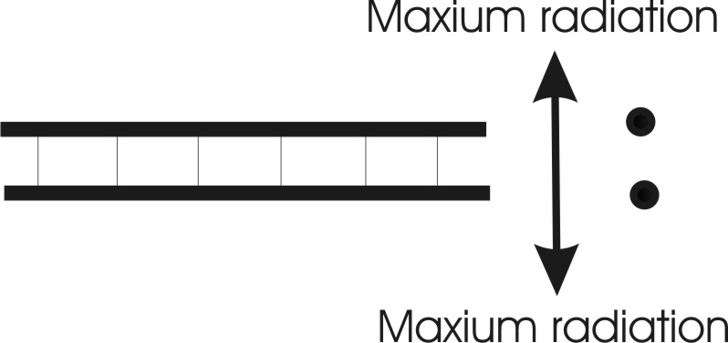
Even with perfect balance in a two-conductor unshielded line, some radiation occurs. The small spatial separation prevents perfect cancellation of far field radiation. The conductors carrying out-of-phase currents are not occupying the same physical space, causing a very small spatial phase delay. This means in two directions radiation fields are not precisely 180 degrees out-of-phase. The amount of phase error, and thus the level of radiation, is a function of conductor spacing in wavelengths and the direction from the line. This effect is minimized by twisting the feedline at small fractions of a wavelength.
Radiation from a perfectly terminated six-inch spaced 50-foot long two-wire transmission line on 80 meters.
Radiation of the same line at 30 MHz is 24 dB stronger. This is because the conductor spacing in wavelengths is wider.
In order to be balanced, a balanced transmission line must have both equal and opposite voltages at any particular point along the line as well as equal and exactly opposite currents at any particular point along the line. If the voltage is not equal and opposite, current cannot remain equal and opposite along the balanced transmission line. This will result in a very large increase in feedline radiation because the imperfection causes common mode currents.
In order to be unbalanced, an unbalanced transmission line must have equal and exactly opposite currents entering and leaving at every point along the line. The voltage gradient laterally along the outside of the transmission line has to be zero. If either the lateral voltage gradient is not zero, or currents entering the line are not equal and opposite on the shield and center, current will not remain zero on the outside of the shield. This will result in common-mode shield currents and feedline radiation.
To avoid feedline radiation every balanced to unbalanced transition has to be properly treated for level and phase of voltage and current.
To be properly balanced, the following must occur:
Voltages from 1 to A, and from 2 to A, must be equal and opposite
Currents into 1 and 2, at the source, must be equal and opposite
Voltages from 1 to C, and from 2 to C, at the load must be equal and opposite
Currents out of 1 and 2, at the load, must be equal and opposite
Voltages all along the line, at any point, to B must be equal and opposite
Common Mode Excitation
Common-mode current is current that is not opposed or counteracted by an equal and opposite phase current flowing at every point along the line in closely-spaced conductor or conductors, and the outside of the shield has current flowing in a coaxial line.
Any transmission line becomes at least partly, a radiating conductor if we make a poor balanced to unbalanced transition. This can be useful when we wish to use a feedline as an antenna or as a conventional conductor, but it can be detrimental to a system if we do not want radiation or reception by our feedlines. When we excite a cable as shown below, we have common mode current:
The common mode source is end-to-end on one or more conductors of twinlead
The common mode source is end-to-end on one or more conductors in a twisted pair of wires
The common mode source is end-to-end on the center, the shield, or both conductors in coaxial or shielded cables.
When we excite a transmission line as shown below we create common-mode current:
The shielded coaxial cable (top) and the parallel conductor cable (bottom) in this diagram radiates just like a single wire would do. Objects surrounding the line, like dielectrics or other conductors, couple to or interact with these lines when they are fed or excited this way. For example, adding a ferrite sleeve over the lines will add loss and/or make the lines behave differently. The impedance of the system will change, and if we are watching system SWR the SWR will change.
This is true even when currents are equal in the two conductors, and can even be true when currents are equal and opposite at one point in the system, so long as the line is excited this way.
The key to having a line behave like a transmission line is feeding it differentially (across the two conductors) at one end, having a load that maintains the differential excitation, and not applying a voltage or a potential difference across the length of one or both conductors.
This is a transmission line as we generally know it, and as dozens of reputable engineering textbooks define it:
This is differential mode, or TEM mode. This is the normally desired excitation mode when a two-wire line behaves like a normal non-radiating line that transfers energy from one point to another.
The above configuration shows a direct wire connection from source to load. It transfers voltage, current, or impedance directly along the conductors.
Dipoles and Common Mode
1/8 wave high dipole
A 1/8th wave long (35 feet in this case) coaxial feedline to the ground point on a dipole often does not need a balun! Here are feeder common mode currents for this case:
| location | amperes |
| Left leg | 0.953 |
| source | 1.000 |
| Right leg | 1.001 |
| 1 ft | 0.052 |
| 2 | 0.054 |
| 3 | 0.056 |
| 4 | 0.057 |
| 5 | 0.058 |
| 6 | 0.060 |
| 7 | 0.061 |
| 8 | 0.062 |
| 9 | 0.064 |
| 10 | 0.065 |
| 11 | 0.066 |
| 12 | 0.067 |
| 13 | 0.068 |
| 14 | 0.069 |
| 15 | 0.070 |
| 16 | 0.071 |
| 17 | 0.072 |
| 18 | 0.073 |
| 19 | 0.073 |
| 20 | 0.074 |
| 21 | 0.075 |
| 22 | 0.075 |
| 23 | 0.076 |
| 24 | 0.077 |
| 25 | 0.077 |
| 26 | 0.078 |
| 27 | 0.078 |
| 28 | 0.078 |
| 29 | 0.079 |
| 30 | 0.079 |
| 31 | 0.079 |
| 32 | 0.079 |
| 33 | 0.079 |
| 34 | 0.079 |
| 35 ft | 0.079 |
Maximum feeder common mode is only .079 amperes (out of a 1 ampere source current) with very good antenna current balance. This is without any balun!
The same dipole 1/4 wave high:
| location | amperes |
| left side | 0.996 |
| source | 1.000 |
| right side | 1.002 |
| shield at dipole | 0.018 |
| 4 | 0.015 |
| 6 | 0.012 |
| 8 | 0.012 |
| 10 | 0.012 |
| 12 | 0.014 |
| 14 | 0.017 |
| 16 | 0.021 |
| 18 | 0.024 |
| 20 | 0.028 |
| 22 | 0.032 |
| 24 | 0.035 |
| 26 | 0.039 |
| 28 | 0.042 |
| 30 | 0.046 |
| 32 | 0.049 |
| 34 | 0.052 |
| 36 | 0.055 |
| 38 | 0.058 |
| 40 | 0.061 |
| 42 | 0.064 |
| 44 | 0.067 |
| 46 | 0.069 |
| 48 | 0.071 |
| 50 | 0.073 |
| 52 | 0.075 |
| 54 | 0.077 |
| 56 | 0.079 |
| 58 | 0.080 |
| 60 | 0.081 |
| 62 | 0.082 |
| 64 | 0.083 |
| 66 | 0.084 |
| 68 | 0.084 |
| ground | 0.084 |
Common mode currents are also low with a 1/4 wave feeder. In many or most cases of dipole height between 1/8th and just over 1/4 wavelength, a balun is NOT necessary provided the feedline drops straight down through open air to ground, and the feedline is grounded when it reaches the earth.
Dipole 1/2 wave feeder to ground
| left leg | 0.561 |
| source | 1.000 |
| right leg | 1.080 |
| shield at antenna | 0.521 |
| 8 | 0.516 |
| 12 | 0.507 |
| 16 | 0.495 |
| 20 | 0.478 |
| 24 | 0.458 |
| 28 | 0.435 |
| 32 | 0.408 |
| 36 | 0.378 |
| 40 | 0.345 |
| 44 | 0.309 |
| 48 | 0.271 |
| 52 | 0.232 |
| 56 | 0.190 |
| 60 | 0.148 |
| 64 | 0.106 |
| 68 | 0.066 |
| 72 | 0.039 |
| 76 | 0.054 |
| 80 | 0.092 |
| 84 | 0.133 |
| 88 | 0.175 |
| 92 | 0.217 |
| 96 | 0.256 |
| 100 | 0.294 |
| 104 | 0.330 |
| 108 | 0.363 |
| 112 | 0.393 |
| 116 | 0.420 |
| 120 | 0.444 |
| 124 | 0.464 |
| 128 | 0.480 |
| 132 | 0.492 |
| 136 | 0.500 |
| ground | 0.505 |
Common mode is terrible with 1/2 wave of feedline length to ground. Unwanted common mode current is actually maximum at the ground!! Common mode current flowing into the ground system, or the cabinets of station equipment, is approximately half of the antenna current!! A balun is mandated for this feedline length and grounding.
Common Mode Impedance
One way to measure common mode impedance is to short the feedline terminals and feed the system as a single wire antenna. Here is the common mode impedance of an 80-meter doublet or dipole fed with 99 feet of open wire line on 40 meters.
| -- common mode source impedance-- Frequency = 7.2 MHz Impedance = 98.86 - J 272.3 ohms |
5000 j0 CM balun losses Load 1 Voltage = 216.4 V at -123.54 deg. Current = 0.04327 A at -123.54 deg. Impedance = 5000 + J 0 ohms Power = 9.363 watts Total applied power = 1000 watts Total load power = 9.363 watts Total load loss = 0.041 dB |
----differential mode SOURCE DATA ------ Frequency = 7.2 MHz Source 1 Voltage = 480.7 V at 53.82 deg. Current = 3.524 A at 0.0 deg. (400 ohm system) = 5.359
|
We see that when common mode impedance and differential source impedance is low, even a very simple modest-impedance balun can do a very effective job. When common mode impedances are high at the balun insertion point, an extremely good balun might not do anything at all. The effectiveness of any balun or common mode choke depends heavily on feedline or antenna grounding, feedline routing, and on feedline length.
We have to consider the entire system.