Microsoft Windows Quick Start Guide
1.125 KHz Bandwidth
FreeDV is a HF Digital Voice program for Windows (and Linux) utilizing an FDM modem and an open source low bit rate codec. Compatible with SSB radios, FreeDV provides communications voice audio occupying less than half the bandwidth of conventional SSB.
Some Technical Specs:
- 50 baud 14 QPSK (Quadrature Phase Shift Keying) voice data
- 1 Center BPSK (Binary Phase Shift Keying) carrier with high power for tuning and sync
- Center BPSK carrier at 1500 Hz baseband
- 1.125 KHz spectrum BW with 75Hz carrier spacing
- 1400 bit/s data rate with 1375 bit/s open source Codec 2 with 25bit/s text rate for call ID

PC |

USB Headset - or - |

Radio to PC Interface |
Hardware:
Soundcard(s) and PTT control setup is the same as other digital modes such as PSK31 except DV requires a low cost headset for voice input and output This can be the same type of USB headset used with a laptop or PC for internet chat. A second sound card with mic/speaker may also be used. Like other digital modes, a Radio to PC interface either homemade or purchased is necessary to provide isolation between equipment. To “listen only,” only one sound card is needed.
FreeDV for Windows will execute and run on about any home or laptop PC with a dual core or higher Intel/AMD CPU. Virtual Audio Cables (VAC), as commonly used with SDR radios, is compatible. Dependent upon your hardware interface, one Com Port or USB port is required for PTT Rig Control. Flex and other SDRs may use a virtual com port pair.
Software:

Microsoft Windows files for FreeDV
Download FreeDV for Microsoft Windows from here
Setup:

PC to Radio Interface Connections
For conventional SSB radios, connect the audio cables from the isolation/PTT interface to the PC and Radio input/outputs. Use same connection as PSK31 plus a USB headset for transmitting and receiving voice. If a separate sound card or USB adapter is preferred as the second device, add it and connect a pc type microphone and amplified speakers.
Note: FreeDV must be in “Stop” mode to change Audio and PTT configurations

Tools Audio Configuration – Select Sound Devices
Execute freedv.exe, go to the “Tools” pull down menu and select “Audio Config.” Sound cards/USB adapters, VAC and/or USB headsets found in your PC will be listed. Select the PC’s internal sound card for the “From/To Radio” receive and transmit data. Select the USB headset for the “To Speaker/Headphones – From Microphone” voice out and input. To test the selection, click on the “Rec 2s” tab, look for a deflection in the scope (from the radio’s speaker output audio or from speaking into the mic). Next, click on the corresponding output device and listen for an 800Hz tone followed by a deflection in the scope. Note: If audio levels have not been previously set for use with another digital mode like PSK31, then they will need adjusting to avoid over or under driving your MIC input of your radio or overdriving the input of the sound card MIC or LINE IN. See “Receiving Digital Voice” and “Transmitting Digital Voice” topics for these adjustments.

Tools PTT Config
Under Tools, go to “PTT Config” and select the Com Port for the radio’s PTT control (recommended over use of VOX control). Select comport “x” used between the interface and the PC. Only comports seen by FreeDV are listed. “RTS” is normally used for rig control. If radio
is keyed into transmit after clicking “Apply,” change the polarity to RTS = +V.

Tools Filter and Equalizers
Under Tools, go to “Filter.” To get started, leave LPC post filter in its default. Adjustment of the Equalizer will depend upon microphone and voice characteristics. Early testing has found voice quality may be improved with most microphones by raising the Treble frequency and Gain. Same changes for the Speaker equalization may show improvements also. On-the-air reports and experimentation will be needed to make final adjustments. Look for further documentation on these settings in future releases.

Tools Enter Callsign
Under Tools, go to “Set Callsign.” Enter your call sign and any optional information (name, location, etc.)

Tools Recording Features
Under Tools, options for Recording and Playback are available. Currently, the record/playback files (Mic in) must be sampled at 8 kHz using 16bit samples. Off the air DV may be recorded and played back through the PC speakers. Currently, recordings may not be played back into the radio Mic input.

RX/TX/Analog Control |

Receive Squelch | |
Receiving Digital Voice:
Note: FreeDV must be in “Start” mode to begin receiving. With no FreeDV signal present, waterfall will display some band “noise” indicating sound is being routed to FreeDV’s input. If no noise is observed, slowly raise audio level using Windows sound mixer (Recording MIC or LINE IN).
Listen for activity on 14.236
USB.

FDM FreeDV signal showing selective fading
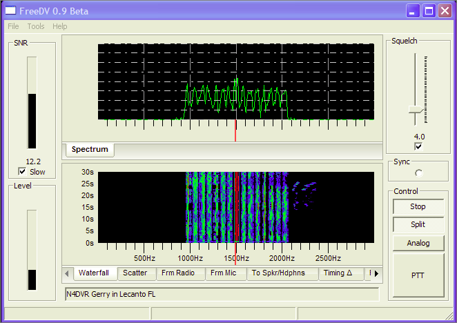
To obtain sync with the transmit signal, close tuning is required but easily accomplished using the mouse while watching the Waterfall or Spectrum displays. Simply left click on the “Red Vertical Line” at the bottom of the display and move it until centered within the two “tracks” of the BPSK (same waterfall appearance as PSK31) sync signal. Instantly, the signal will sync (if SNR is 4 or higher) and the voice will be decoded and heard in the headset or speakers. Once in sync, the radio’s frequency dial should not be moved. FreeDV’s AFC will correct for any signal drift. The input level from the radio to FreeDV input should be set so the waterfall is blue (white indicates level is too high and the “Level” bubble will flash a warning). Various signal levels within the waterfall with show as different colors of blue, white and red.
Note: Window’s mixer sliders are used for level adjustments. For SDR radios with Virtual Audio Cables, use the application’s software adjustments.

Signal Displays showing minimum fading and high SNR
Various displays are available to view the received signal. Default display is the waterfall. Click on the tabs below for more. On transmit; the “Frm Mic” O’scope is used for showing input audio from the Mic. To add 2 or more displays, left click on the display tab and drag vertically to the top. Release the left click button when a blue background is seen in the display area. Displays can be arranged in various horizontal and vertical positions depending on location within the window the cursor is released. Technical documentation for interpreting these displays will be provided in future releases. Waterfall color may be changed to monochrome or all blue with a right click inside the display window.
Note: Tune the signal to 1500Hz which will be in the center of the Waterfall/Spectrum display and your radio’s transmit band pass. Refer to the graphics.
Squelch: Checked box activates squelch with a default of 4dB. This level is approximately the lowest SNR for which the modem will provide dropout free voice decoding with a “no noise” background. However, experience has found decoding of lower SNR signals is possible in multipath/fades and QRM by taking advantage of the fast recovery/sync of FreeDV. Unchecked will allow “listening on the frequency” in analog mode when no digital signal is being decoded. Experiment with the settings in different signal and noise conditions.
")
Oscilloscope Transmit Display (Frm Mic)
Transmitting Digital Voice:
If not started, click on “Start” and then “PTT.” Quickly, verify the RF output level, and then watch the Scope display while speaking in a normal loudness voice for approximately 75% maximum deflection. Too high voice input may cause clipping. Adjust RF power for approximately 25w average with a 100w transceiver. This is an important setting to avoid distortion and reducing the SNR at the receiving station. If necessary, lower the drive until no ALC action is noted.
Tip: Call sign/name text data is being sent at a low bit rate (25bit/sec). When initializing a contact (calling a station) transmit for 10-15 seconds minimum to ensure the receiving station is tuned in and received the callsign text.
Analog:
This bypasses encoding/decoding and routes the Mic audio to the transmitter’s Mic and the receive audio from the speaker. Monitoring of the frequency may now be made and analog (SSB) transmissions. Some adjustments in the audio drive to the Mic may be required for full analog output.
Other Features:
Split allows independent tuning of the RX frequency without affecting the transmitter’s frequency. This is useful in three-ways and nets to avoid changing the transmit frequency for stations entering the QSO not on the established frequency.
(future) TX-ID and RX-ID is a MFSK mode ID, auto-sync and alarm feature that will be implemented in a future release.
SNR is shown both in a visual indicator and numerically. Since SNR will continually fluctuate (sometimes rapidly) over an HF channel, it can be averaged using the “Slow” option (default). SNR of approximately 4dB is required to begin decoding without voice dropouts. As the SNR increases with stronger signal levels, no dropouts and good communications quality voice will be experienced. Expect SNR of 10-14dB while receiving an S9 signal. Several variable factors contribute to this reading both at the transmitting and the receive station.

Receive Text Box
The transmitted text info (call sign, name, etc) is displayed near the bottom of the GUI in a continuous loop. No text data may be entered here, only displayed from the transmitting station. Use Tools>Set Call Sign to enter data into the text box.
Operating Tips:
Begin by looking for activity on 20m, 14.236 in the US. FreeDV’s FDM carriers make a distinctive noise and but are only 1125 Hz wide. Avoid confusing the “noise” heard 3 KHz down at 14.233 which is the digital-SSTV frequency for picture transfers which is over twice the bandwidth.
To avoid unwanted “non-voice” noise decoded by the listener (typically a sound like “bees buzzing around”); ensure no RFI ingress into the sound card inputs. Ferrites can help at the inputs. AC riding on the interface cables may also be picked up, transmitted and decoded. Poor grounding practices may cause this type of noise problem. Voice quality may be dependent on the type of microphone but low cost PC “electret” Mics can provide good voice audio. Logitech and Altec Lansing HS have good low cost models. The equalizer can improve the audio.
Look for weekend nets around 1800utc 14.236 USB. Call in on SSB for help. Join yahoo’s “digitalvoice” group for support. Check freedv.org often and n1su.com for DV developments.
KØPFX 07-Dec-12 Rev 0.9